
Home / Filter Press Products / Gasketed CGR Filter Press
CAULKED CLOTH / GASKETED RECESSED PLATES
Gasketed CGR Filter Press
Reduce cloth-edge wicking and plate-edge leakage with a matched gasketed plate and cloth assembly. Select the sealing materials, plate pack and operating conditions around your slurry and filtrate-recovery requirements.
Send the liquid chemistry, concentration, temperature, pressure and required production rate.
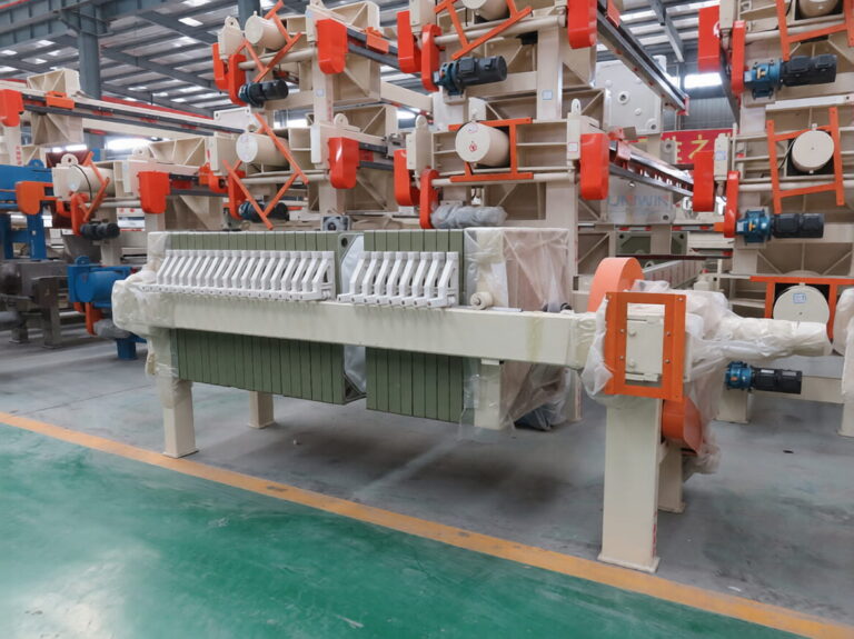
CGR plate design
Caulked • Gasketed • RecessedCloth retention, sealing and chamber geometry work together.
Published filtration pressure
≤0.6 MPaSupplier table value, equivalent to ≤6 bar; confirm the selected assembly.
Selection priority
Cloth + gasket fitMatch the plate groove, cloth edge and gasket compound to the duty.
How the CGR Plate and Cloth Assembly Seals
CGR stands for Caulked, Gasketed, Recessed. Compared with cloth draped over a plate’s sealing edge, the CGR arrangement retains the cloth edge in a groove and uses dedicated sealing features between plates.
Caulked cloth
A shaped cloth edge is seated in the matching plate groove. Correct dimensions and installation help keep the cloth in place without extending it across the perimeter sealing face.
Gasketed sealing
Gaskets at the plate perimeter, and at ports where required by the design, help reduce leakage. Confirm their location and compound on the proposed plate drawing.
Recessed chambers
Recesses create the space where retained solids form a cake. The gasketed design changes the sealing arrangement; it does not itself add a membrane-squeezing stage.
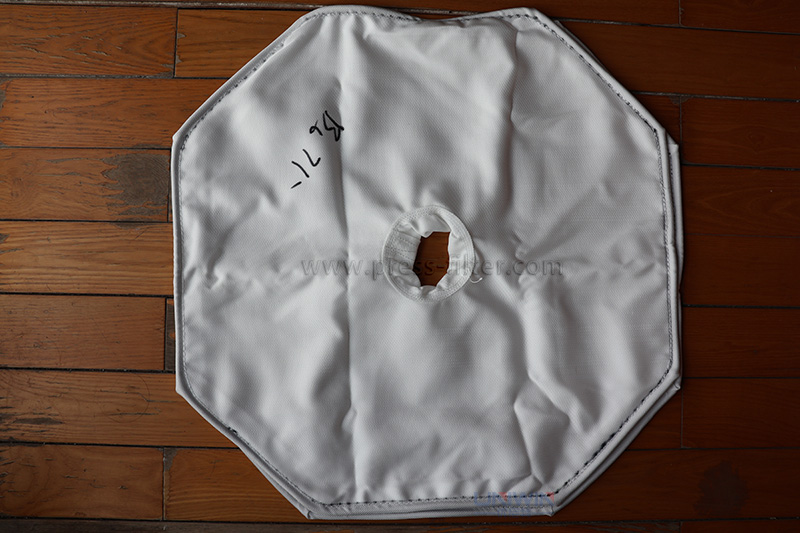
Shaped cloth with a retained edge
Supplier cloth example. Specify the plate drawing, cloth dimensions, feed opening and edge-retention detail when ordering replacements.
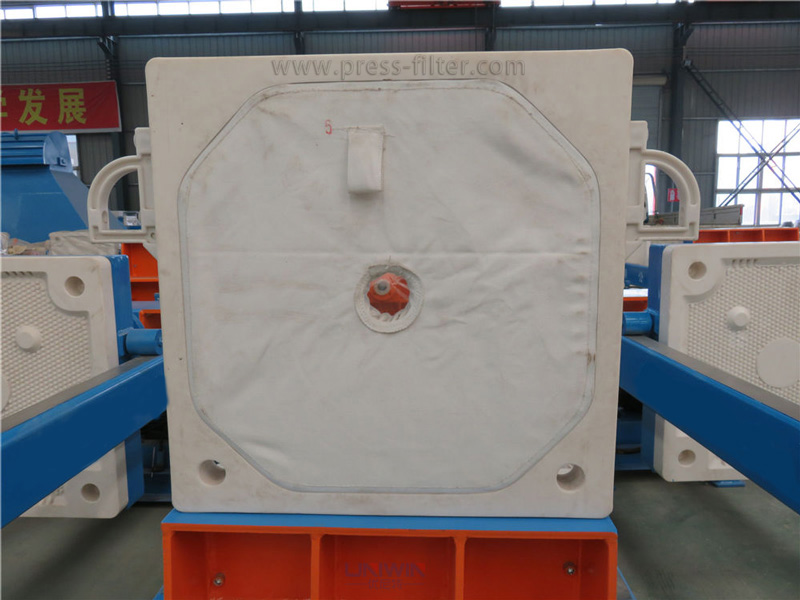
Cloth fitted to the plate
Supplier plate example with fitted cloth. Confirm the actual perimeter and port seals; photographs do not establish a pressure or containment rating.
Sealing performance depends on gasket compatibility, cloth fit, clean sealing faces, alignment and closing conditions. A gasketed plate pack is not, by itself, a gas-tight enclosure or a guarantee of zero evaporation.
Supplier BMY Reference Specifications
The supplier publishes the following 17 BMY entries on its CGR product page. Use the table for an initial size comparison, subject to confirmation that the chosen entry matches the proposed CGR assembly.
Confirm the table against the plate-pack drawing. Although the product is described as recessed CGR, the table includes a “Number frame” column. The /450 and /630 plate sizes differ from the model codes, while the /890 rows list 35 mm cake thickness with “-30U” model suffixes. These source values are retained and highlighted.
BMY /450 reference family
7 source entries · 4–16 m² listed area
Source plate-size entry: 500 × 500 mm. Verify the selected plate drawing.
| Published model | Filter area (m²) | Published plate size (mm)* | Cake thickness (mm)* | Chamber volume (L) | Plates (pcs) | Published frame count* | Filtration pressure (MPa) | Listed motor power (kW)* | Weight (kg) | Dimensions L × W × H (mm) |
|---|---|---|---|---|---|---|---|---|---|---|
| BMY4/450-30U | 4 | 500*500 | 30 | 60 | 9 | 10 | ≤0.6 | 2.2 | 860 | 2080*800*900 |
| BMY6/450-30U | 6 | 500*500 | 30 | 91 | 14 | 15 | ≤0.6 | 2.2 | 910 | 2380*800*900 |
| BMY8/450-30U | 8 | 500*500 | 30 | 121 | 19 | 20 | ≤0.6 | 2.2 | 960 | 2680*800*900 |
| BMY10/450-30U | 10 | 500*500 | 30 | 151 | 24 | 25 | ≤0.6 | 2.2 | 1010 | 2980*800*900 |
| BMY12/450-30U | 12 | 500*500 | 30 | 182 | 29 | 30 | ≤0.6 | 2.2 | 1060 | 3280*800*900 |
| BMY15/450-30U | 15 | 500*500 | 30 | 225 | 36 | 37 | ≤0.6 | 2.2 | 1130 | 3700*800*900 |
| BMY16/450-30U | 16 | 500*500 | 30 | 243 | 39 | 40 | ≤0.6 | 2.2 | 1160 | 3880*800*900 |
BMY /630 reference family
4 source entries · 15–40 m² listed area
Source plate-size entry: 700 × 700 mm. Verify the selected plate drawing.
| Published model | Filter area (m²) | Published plate size (mm)* | Cake thickness (mm)* | Chamber volume (L) | Plates (pcs) | Published frame count* | Filtration pressure (MPa) | Listed motor power (kW)* | Weight (kg) | Dimensions L × W × H (mm) |
|---|---|---|---|---|---|---|---|---|---|---|
| BMY15/630-30U | 15 | 700*700 | 30 | 226 | 18 | 19 | ≤0.6 | 2.2 | 1725 | 2840*1000*1100 |
| BMY20/630-30U | 20 | 700*700 | 30 | 297 | 24 | 25 | ≤0.6 | 2.2 | 1993 | 3200*1000*1100 |
| BMY30/630-30U | 30 | 700*700 | 30 | 452 | 37 | 38 | ≤0.6 | 2.2 | 2360 | 3980*1000*1100 |
| BMY40/630-30U | 40 | 700*700 | 30 | 595 | 49 | 50 | ≤0.6 | 2.2 | 2788 | 4800*1000*1100 |
BMY /890 reference family
6 source entries · 30–80 m² listed area
Source cake-thickness entry: 35 mm. Model suffix remains -30U; confirm the actual chamber depth.
| Published model | Filter area (m²) | Published plate size (mm)* | Cake thickness (mm)* | Chamber volume (L) | Plates (pcs) | Published frame count* | Filtration pressure (MPa) | Listed motor power (kW)* | Weight (kg) | Dimensions L × W × H (mm) |
|---|---|---|---|---|---|---|---|---|---|---|
| BMY30/890-30U | 30 | 890*890 | 35 | 524 | 23 | 24 | ≤0.6 | 2.2 | 2580 | 3740*1385*1300 |
| BMY40/890-30U | 40 | 890*890 | 35 | 677 | 30 | 31 | ≤0.6 | 2.2 | 2925 | 4220*1385*1300 |
| BMY50/890-30U | 50 | 890*890 | 35 | 852 | 38 | 39 | ≤0.6 | 2.2 | 3318 | 4880*1385*1300 |
| BMY60/890-30U | 60 | 890*890 | 35 | 1027 | 46 | 47 | ≤0.6 | 2.2 | 3712 | 5440*1385*1300 |
| BMY70/890-30U | 70 | 890*890 | 35 | 1201 | 54 | 55 | ≤0.6 | 2.2 | 4106 | 6000*1385*1300 |
| BMY80/890-30U | 80 | 890*890 | 35 | 1376 | 62 | 63 | ≤0.6 | 2.2 | 4561 | 6560*1385*1300 |
*The “frame count” label is reproduced from the source and does not confirm that separate chamber-forming frames belong in the proposed CGR pack. The shared 2.2 kW entry is not a verified complete-system electrical load. Confirm the model, plate construction, chamber depth, motors, weight and dimensions in the quotation.
Source merged cells have been expanded for readability. Table filtration pressure is ≤0.6 MPa (≤6 bar), separate from hydraulic closing pressure. Swipe within the tables on smaller screens.
Reference: supplier gasketed CGR filter press specifications, reviewed 30 September 2026.
Choose the Gasket and Filter Cloth for the Actual Chemistry
Gasket compound
Provide the chemicals, concentrations, temperature, exposure duration and cleaning agents. Ask for the offered elastomer grade and compatibility data for the complete mixture.
Cloth and edge profile
Specify fabric, permeability or separation requirements, feed-hole arrangement and the retaining edge. Confirm dimensions against the plate drawing and the required filtrate quality.
Assembly and acceptance
Agree operating limits, closing conditions and the inspection or test procedure used to check sealing. Include ports, connections, valves and filtrate routing in the review.
A generic label such as EPDM, NBR, FKM or silicone is not a complete material specification. Availability, grade and suitability require confirmation; no one compound is suitable for all solvents, acids or cleaning conditions.
CGR and Non-Gasketed Recessed Plates
| Compare | CGR arrangement | Non-gasketed arrangement |
|---|---|---|
| Cloth fitting | Shaped cloth edge retained in the matching groove. | Cloth commonly drapes across the plate; confirm the specific plate design. |
| Edge sealing | Dedicated gaskets help control leakage when properly selected and maintained. | Cloth-edge wicking or drips may occur, depending on the plate, medium and operating conditions. |
| Maintenance focus | Grooves, gasket condition, fitted cloth dimensions and sealing faces. | Cloth fit and condition, plate faces and any drip collection arrangement. |
| Decision basis | Evaluate when control of edge leakage and filtrate recovery are important. | Evaluate against the same slurry, cleanliness requirements and complete operating cost. |
Retrofitting requires a review of plate supports, plate-pack length, feed and filtrate connections, closing force, stroke and controls. Do not assume a gasketed cloth alone can convert a standard plate into a CGR plate.
Cloth Installation and Seal Inspection
01
Prepare the plate
Isolate and depressurize the equipment as instructed. Clean the grooves and sealing faces; inspect plates, gaskets and the replacement cloth before fitting.
02
Fit the matched cloth
Align the feed opening and seat the retaining edge using the equipment maker’s procedure and suitable tools. Keep folds, particles and damage away from the sealing surfaces.
03
Reassemble and check
Reassemble the plate pack in the correct order and carry out the specified check cycle. Inspect for leakage and correct its cause before returning to normal duty.
Replacement intervals depend on wear, chemistry, cleaning and process conditions. Confirm exact cloth and gasket part numbers; do not trim or modify a fitted cloth unless the equipment procedure explicitly requires it.
Applications Where Seal Control Matters
Chemical processing
Define slurry chemistry, cleaning agents and the required control of drips and product loss. Confirm the entire flow path, gasket compound and equipment specification.
Mining and wastewater
Review fine solids, abrasive particles, conditioning chemicals and cake handling. Maintain clean plate edges and grooves throughout repeated batch cycles.
Food and process liquids
Define contact-material requirements, filtrate quality and the cleaning procedure. Gasketed construction alone does not establish sterile operation or process compliance.
For volatile, flammable or hazardous materials, define containment, ventilation and any required equipment approvals for the full system. A CGR plate seal alone does not substantiate those capabilities.
Gasketed CGR Filter Press FAQs
What does CGR stand for?
CGR means Caulked, Gasketed, Recessed. It describes cloth retention, the sealing arrangement and the recessed chamber geometry of the filter plates.
Does CGR guarantee zero leakage or zero evaporation?
No unconditional guarantee follows from the CGR name. Leakage depends on gasket condition, chemical compatibility, cloth fit, clean sealing faces, alignment and operating conditions. Gas containment and evaporation control require a separate system assessment.
Which gasket material should I choose?
Supply the complete chemical mixture, concentrations, temperatures and cleaning conditions. Select a specific offered compound using compatibility information, mechanical requirements and any necessary testing, rather than broad rules such as one material for all solvents.
Why does the reference table include a frame count?
The supplier’s CGR page contains that column in its BMY table. Its applicability to a recessed CGR assembly is not established by the table alone. Request the confirmed model and plate-pack drawing before ordering.
Can the press perform vacuum drying or sterile filtration?
The reference product information does not substantiate either capability. Vacuum service, sterile filtration, validation and supporting documentation must be specified and confirmed for the complete configuration.
Can an existing press be converted to CGR?
Possibly, subject to an engineering review. Plate geometry, pack length, supports, cloth, seals, feed and filtrate routing, closing system and controls must be compatible. A replacement plate pack is not automatically a drop-in fit.
GASKET, CLOTH & PLATE-PACK SELECTION
Request a Gasketed CGR Filter Press Proposal
Send the slurry chemistry, concentrations, temperature, throughput with units, solids content and required filtrate quality. Describe the leakage or product-recovery requirement.
Include cleaning agents, operating pressure, utilities and project location. For replacement cloths or a retrofit, provide the existing plate drawing and full machine details.
Confirm model data, gasket compound, cloth drawing and sealing acceptance conditions in the quotation.