The answer to calculate filtration area of filter press starts with multiplying the effective area of one filtering face by the number of active filtering faces: A = a × S. To size a new press, calculate the area needed to hold the cake from each batch, then check whether the press can complete enough batches to meet your production target.
| What you need | Calculation | Important condition |
|---|---|---|
| Installed filtration area | A = a × S | a is effective area per face in m²; S counts active faces. |
| Area from identical chambers | A = 2 × a × n | n counts chambers, each with two active filtering faces. |
| Area from cake volume | A ≈ 2 × Vc ÷ δ | Vc is cake volume in m³; δ is full chamber thickness in meters; area includes both faces. |
| Area from tested productivity | A = R ÷ q | R is dry-solids demand in kg/h; q is validated full-cycle productivity in kg/(m²·h). |
These calculations answer different questions. Use the first two to check an existing plate pack. Use the last two together when selecting equipment for a process.
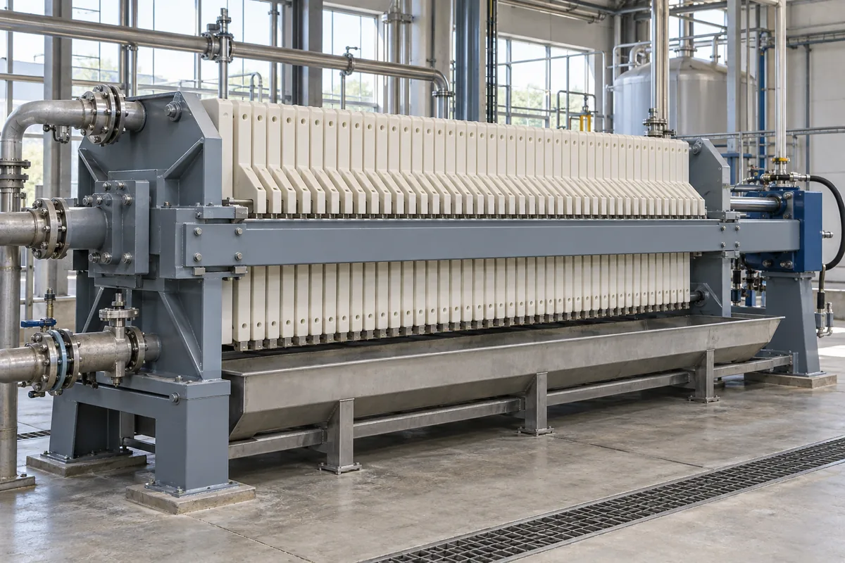
Quick Summary:
Calculate installed filtration area with A=a×S, where a is the effective area of one filtering face and S is the number of active faces. For identical chambers, use A=2×a×n, while approximate area from cake volume is A≈2×Vc÷δ.
For new equipment, calculate dry-solids demand, available complete cycles, wet cake volume and chamber-volume requirements. Then verify the result with tested full-cycle productivity using A=R÷q, and confirm effective area, usable chamber volume and achievable cycle time with the supplier.
Know What Filtration Area Actually Measures
Filtration area measures the effective cloth surface through which liquid passes, usually expressed in square meters. Chamber volume measures the space available to hold cake, usually expressed in liters or cubic meters.
Both matter. A press can have enough chamber space but take too long to dewater its contents. It can also filter quickly but need too many discharge cycles to handle the daily solids load.
The daily capacity depends on the amount processed per cycle and the number of cycles completed.
Start by writing down your actual objective: checking an installed machine, replacing a plate pack, or sizing a new press. That choice tells you which inputs to collect.
How to Calculate Filtration Area of Filter Press?
1. Calculate the Effective Area of One Face
Use the active filtering dimensions from the plate drawing or the manufacturer’s stated effective area. The outside dimensions of a plate can include sealing borders and other sections that do not provide usable filtration area.
An “800 mm plate” therefore does not automatically provide 0.64 m² of effective filtering surface on each side.
For a practical specification check, compare the published filtration area and chamber volume in these recessed chamber filter press specifications. Confirm the exact plate pack before using either value.
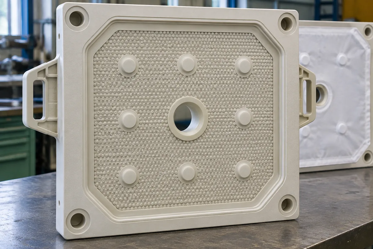
Use the Active Dimensions and Consistent Units
For a rectangular active face, multiply its effective width by its effective height, then account for nonfiltering features identified on the drawing. For a circular face, start with π × diameter² ÷ 4 and make the appropriate deductions.
Suppose a simplified rectangular face measures 600 mm × 600 mm, with 0.010 m² of specified nonfiltering area:
- Convert the dimensions: 600 mm = 0.600 m.
- Calculate the rectangle: 0.600 × 0.600 = 0.360 m².
- Subtract the excluded area: 0.360 − 0.010 = 0.350 m² per face.
This is an illustrative calculation, not a specification for a commercial plate. Real recesses, feed openings and support features can make the geometry more complicated.
If the supplier already gives effective area, use it directly. Subtracting the same excluded sections again would understate the result.
Count Active Faces, Not Just Plates
Multiply the effective face area by the actual number of working faces in the assembled pack. Doubling the plate count works only when every counted plate contributes two active faces and the end arrangement has been handled correctly.
For a pack with 20 identical chambers and two active faces per chamber:
A = 0.350 × 2 × 20 = 14.0 m²
Check the assembly drawing before turning that chamber count into a plate count. Head plates, tail plates, blanking plates and the supplier’s counting convention can change the relationship.
My recommendation: ask for total effective filtration area and total chamber volume on the same quotation. Those two figures are more useful than nominal plate size alone.
2. Convert Chamber Volume Into Filtration Area
For an ideal chamber filtering through both opposing faces, total area is approximately twice the cake volume divided by the full chamber thickness. This gives A ≈ 2 × Vc ÷ δ, with Vc in cubic meters and δ in meters.
The factor of two comes from the geometry. A chamber with a 1 m² footprint and a 0.030 m depth holds approximately 0.030 m³ of cake, but its two filtering faces provide 2 m² of area.
Rearranging the relationship gives:
Vc ≈ A × δ ÷ 2
At 30 mm thickness, each square meter of total two-sided filtration area corresponds to approximately 15 liters of chamber volume.
Be precise about “cake thickness.” Here, it means the full cake thickness between opposing filtering surfaces. If a calculation uses the thickness of the layer growing from one face, its convention is different.
Manufacturer drawings and published area-to-volume data take priority over this idealized estimate. Membrane movement and internal geometry can change usable volume.
3. Size the Area for Your Daily Solids Load
Calculate daily dry solids, divide by achievable cycles, and convert the solids in each batch into wet cake volume. Then convert that volume into area using the selected chamber thickness.
For wastewater biosolids, the U.S. EPA’s recessed-plate filter press design criteria call for daily solids quantities, feed concentration ranges and seasonal variation. Those inputs help define the load the press must actually handle.
The following example uses illustrative assumptions, not results from an operating plant. It assumes a fixed-volume chamber press, essentially complete capture of the filterable solids, and no additional solids from conditioning chemicals.
Establish the Feed Load and Available Cycles
Daily dry-solids load equals slurry volume multiplied by slurry density and the mass fraction of filterable solids. Use Md = Qd × ρs × wf.
Assume:
- Daily slurry volume, Qd: 60 m³/day.
- Slurry density, ρs: 1,050 kg/m³.
- Feed solids by mass, wf: 4%, entered as 0.04.
- Available operating time: 12 hours/day.
- Complete cycle time: 1.5 hours.
The daily solids load is:
Md = 60 × 1,050 × 0.04 = 2,520 kg/day
At 1.5 hours per complete cycle, the press can finish:
N = 12 ÷ 1.5 = 8 cycles/day
That puts 315 kg of dry solids in each batch: 2,520 ÷ 8.
Use hours actually available for production. Include routine closing, filling, filtration, squeezing if applicable, opening, discharge and cleaning time in the cycle estimate. The filter press working-cycle animation helps identify those separate stages. Account for downtime once; don’t subtract it from available hours and also charge it again inside every cycle.
If a shift cannot accommodate a partial cycle, round the number of completed cycles down. A continuous operation may use a different scheduling basis.
Convert Dry Solids Into Wet Cake Volume
Divide dry solids per batch by the cake solids mass fraction, then divide by measured wet cake density. Use Vc = Mc ÷ (wc × ρc), where Mc is dry solids per cycle.
Assume the cake contains 35% solids by mass, and its wet bulk density is 1,250 kg/m³.
The calculation becomes:
Vc = 315 ÷ (0.35 × 1,250) = 0.72 m³ per cycle
That is 720 liters of cake space.
Notice that 35% cake solids means 65% moisture on a wet mass basis. Entering 65% as the solids fraction would produce the wrong chamber requirement.
Wet cake density also differs from the density of the solid particles themselves. Use a representative cake measurement at the relevant process condition.
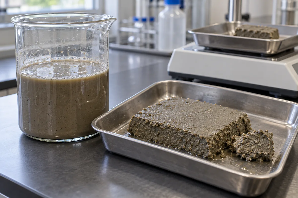
For membrane filter presses, final squeezed cake volume can be smaller than the volume needed before squeezing. Check the chamber filling condition and membrane displacement with the supplier before using final cake measurements for selection.
Calculate Area and Apply a Documented Margin
At a full chamber thickness of 30 mm, the example requires approximately 48 m² before any design margin. Convert 30 mm to 0.030 m before calculating.
A ≈ 2 × 0.72 ÷ 0.030 = 48 m²
For this example only, assume a 20% allowance for specified load variation:
Design area = 48 × 1.20 = 57.6 m²
The corresponding chamber-volume target is 864 liters at the same thickness.
This allowance is an assumption, not an industry-wide rule. Kanadevia’s guidance ties the safety factor to slurry variability and the consequences of insufficient capacity. Set yours from the actual operating range and test evidence.
Also check how a larger press will fill at normal and minimum loads. Extra installed capacity can require different batch sizes or cycle settings.
Use This Filter Press Sizing Chart to Compare Options
The Filter Press Sizing Chart below converts total two-sided filtration area into approximate chamber volume at several full cake thicknesses. Use it to compare geometry after establishing your process requirements.
| Total filtration area | 25 mm cake | 30 mm cake | 32 mm cake | 40 mm cake |
|---|---|---|---|---|
| 10 m² | 125 L | 150 L | 160 L | 200 L |
| 25 m² | 312.5 L | 375 L | 400 L | 500 L |
| 50 m² | 625 L | 750 L | 800 L | 1,000 L |
| 75 m² | 937.5 L | 1,125 L | 1,200 L | 1,500 L |
| 100 m² | 1,250 L | 1,500 L | 1,600 L | 2,000 L |
Every cell follows volume in liters ≈ area in m² × thickness in mm ÷ 2. No slurry throughput is implied by these numbers.
For the worked example, a 50 m² press with 30 mm chambers offers about 750 liters. It exceeds the base 720-liter estimate but falls short of the assumed 864-liter design target.
You would therefore request a configuration meeting both the specified area and volume, then confirm its operating performance.
Commercial charts have their own assumptions. For example, Micronics’ sizing chart states that its guidance is based on 32 mm cake chambers. Comparing it with a 40 mm design without adjusting the volume basis can mislead you.
4. Check Whether the Press Can Finish on Time
Validate required area against dry-solids productivity measured over a complete operating cycle. Enough space to hold the cake does not establish how quickly the slurry will filter.
The University of South Carolina’s plate-and-frame filtration theory separates cloth resistance from cake resistance, which increases as cake builds up. That explains why an early flow reading cannot represent the entire batch.
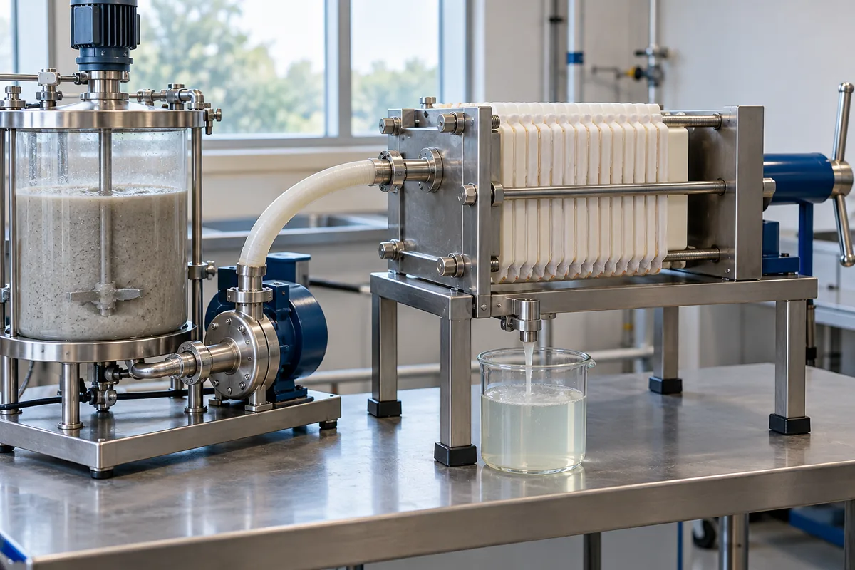
Use these relationships:
- q = dry solids captured ÷ (test filtration area × complete cycle time).
- R = daily dry-solids demand ÷ available operating hours.
- Required area = R ÷ q.
Keep q in kg/(m²·h) and R in kg/h. The resulting area is in m².
In the worked example, R is 2,520 ÷ 12 = 210 kg/h. The preliminary 48 m² calculation implicitly requires a full-cycle productivity of 210 ÷ 48 = 4.375 kg/(m²·h).
That value is a target derived from the assumptions. It is not a measured filtration rate.
If representative testing cannot support it, revisit the area, chamber thickness, batch size and operating schedule. Once those choices change, recalculate the full cycle and chamber requirement together.
Include Discharge, Washing and Other Cycle Steps
Use the complete cycle when turning a test result into hourly productivity. A rate calculated from filtration time alone will overstate the throughput of a batch machine.
For example, suppose a test captures 6 kg of dry solids per square meter in 45 minutes of filtration. Dividing by 0.75 hours gives 8 kg/(m²·h).
But if the complete cycle takes 90 minutes, the usable productivity is:
6 ÷ 1.5 = 4 kg/(m²·h)
For the same hourly demand, the filtration-only calculation would suggest half the area required by the complete-cycle calculation.
Match the test to the intended cloth, chamber thickness, pressure program, slurry temperature and cake endpoint. When choosing a laboratory filter press for testing, check that its pressure range and configuration can reproduce the conditions relevant to your production process. Allow for how discharge and cloth washing will actually work on the production machine.
5. Verify the Inputs Before Choosing a Plate Pack
Confirm effective area, usable chamber volume and achievable cycle time for the same proposed configuration. These three checks connect the calculation to a machine that can meet the production requirement.
Send the supplier a short sizing sheet containing:
- Normal and peak slurry volume, plus feed density and filterable solids concentration.
- Target cake solids and the basis for wet cake density.
- Available operating hours and the required daily dry-solids throughput.
- Slurry variability, conditioning chemicals and cake-washing requirements.
- Selected chamber thickness and the assumed design allowance.
- Representative filtration results, including complete-cycle timing.
- Space, access, discharge clearance and utility constraints.
Ask the supplier to state whether quoted area includes both filtering faces, how plates and chambers are counted, and which volume applies before and after membrane squeezing.
For preliminary comparison, evaluate both the chamber-volume requirement and the tested productivity requirement. Choose a configuration satisfying both, then confirm that it operates properly across the expected load range.
The broader guide to choosing filter press size connects these calculations with plate selection, pump duty and site layout.
Avoid These Errors in Your Calculation
The most consequential mistakes are using the wrong area convention, mixing concentration units and assuming a cycle time the slurry cannot achieve. Check those inputs before refining decimal places.
- Using outside plate dimensions. Replace them with effective filtering area from the drawing or data sheet.
- Multiplying every plate by two. Verify end plates and count actual active faces.
- Treating 4% as 4. A mass percentage enters the formula as 0.04.
- Confusing mass and volume concentration. If filterable solids are already given in kg/m³ of slurry, multiply directly by slurry volume; don’t multiply by slurry density again.
- Counting dissolved material as retained cake. Use the filterable solids load and account for precipitates or conditioning solids actually captured.
- Assuming thicker cake improves daily output. It increases chamber storage per unit area, but it can also extend filtration time.
- Ignoring units in a shortcut formula. An area calculation must resolve to m², not m³, kg or m³/h.
Keep the operating conditions attached to every test result. A throughput figure without its cloth specification, cake endpoint and cycle definition is difficult to use responsibly.
Put Your Area Calculation to Work
Use effective face area and active-face count to check an existing press; use solids mass balance, chamber volume and complete-cycle testing to size a new one. The worked example gives 48 m² before margin and 57.6 m² with its assumed 20% allowance, subject to validating cycle performance and the selected plate geometry.
Your next step is to replace the example inputs with measured slurry and cake data. Then send your filter press sizing requirements for a proposal that states its area, chamber volume and expected daily throughput on the same basis.